SMD accessories
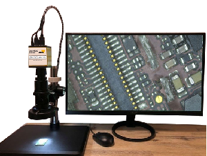
Inspection Camera KIS-IMX290
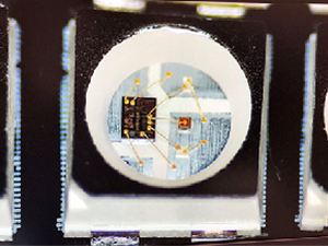
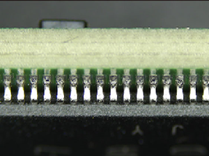
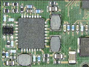
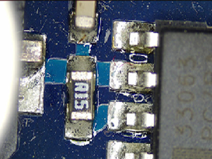
This microscope system provides brilliant image quality without delays on HDMI output. It has a fast zoom and offers wide-range automatic image adjustment.
The depth of field is perfect thanks to the built-in HDR function. PCB repairs and SMT inspections have never been easier.
Manual, optical inspection is used especially for the inspection of small series and prototypes as well as in development. By means of a manual, optical
inspection, almost all defect patterns can be detected and documented. Advantages compared to automated systems are the mostly low investment costs and the
flexibility. Complex programming is not necessary.
Technical data
| Camera |
IMX290 Sony 2.2 MP automatic wide range sensor with BSI zoom and high light sensitivity |
| Lens | 16X-160X adjustable magnification 25 mm zoom C-mount lens 0.7X ~ 5X working distance 110 - 170 mm |
| Pixel | Size 1 / 2,8" |
| Lens mount | C / CS-Typ |
| Display frame rate | 60 Hz at 1080 P |
| Shutter speed | 1/50 s (1/60 s) |
| Exposure | automatic and manual |
| Software features |
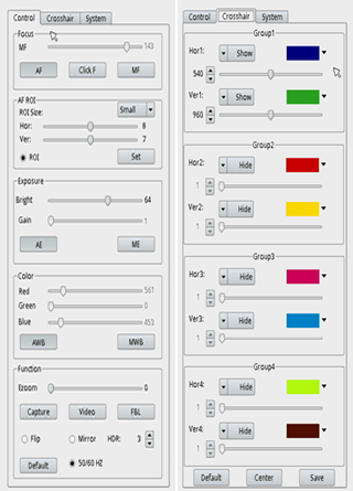
HDR mode, AWB / MWB, color adjustment Save image to micro SD. Save H264 video to micro-SD, add lines horizontally and vertically, real-time clock
|
| Dimensions | 300 x 300 x 250 mm |
| Weight | 5 kg |
| Connection | AC 230 V / 110 V |
Manual inspection with image comparison IBV-1080 P
64 bit processor with 2 GB internal memory Full HD resolution (1920 x 1080 pixels) Zoom lens for optimal use of the display area digital management of
patterns easy operation massive tripod
Technical data
| Controller Type |
64 bit Quad Core ARM |
| Internal memory | 2 GB |
| External memory | USB" |
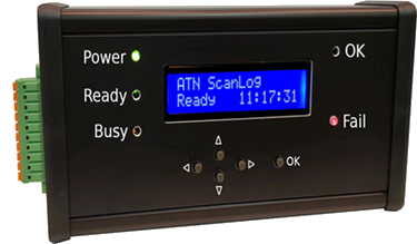
| Interface Operator | Display 2 lines with
20 characters, 5 LEDs, 6 buttons |
| Interface Monitor | HDMI |
| Video recording resolution | 1080 p / Full HD |
| Optical sensor size | 1/2.7" |
| Lens type |
wide angle, zoom (2.8-12 mm)
manual focus and aperture adjustment |
| Working distance and image size |
a= 600 mm
Image 90 x 50 bis 500 x 300 mm
a= 200 mm
Image 50 x 30 bis 200 x 120 mm
|
In SMD series production, the Automatic Optical Inspection (AOI) after the soldering process or the Solder Paste Inspection SPI immediately after solder paste
printing enable a 100 % inspection. However, for sample assemblies or small series, manual visual inspection is required because the programming effort of SPI
and AOI systems is too high. In addition to solder joints, the PCB is checked for the presence, polarity and misalignment of components. The comparison with the
assembly plan or, if already available, with a sample board from the sample cabinet is time-consuming and exhausting and depends on the respective employee. With
the camera system IBV-1080P one can use the characteristic of the human eye to perceive changes fast.
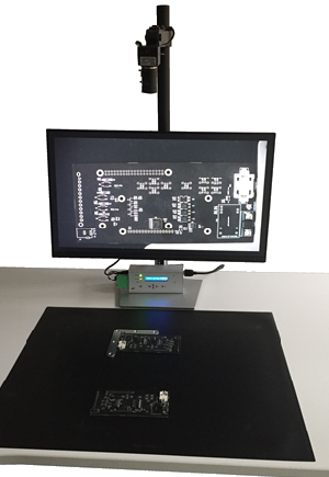
A comparison pattern, also called "Golden Board", is positioned under the camera via stops and the image is saved as a JPG file. Then the specimen is positioned
under the camera. The two images are output alternately on the monitor. For an assembled PCB, it looks to the viewer as if missing components are flashing and
misaligned components are wobbling. However, the method also works for the still unpopulated board and also for boards after solder paste printing. The IBV-1080P
camera system allows images to be stored, i.e. sample board storage can be done electronically, eliminating the need to store samples. Change statuses and defect
images can be easily documented.
For recurring small series, the line release can be done much faster by verifying the correct PCB, by checking the solder paste print and subsequent assembly control. Further fields of application of the IBV-1080P are version comparison of assemblies and assignment of change statuses, incoming inspection of printed circuit boards, outgoing inspection of fully assembled assemblies. The camera system IBV-1080P contributes with simple handling and programming as well as small investment crucially to the quality increase and is in the entire manufacturing process a useful aid for the quality assurance.
| Scope of delivery |
Controller and power supply
2 MP camera (Full-HD)
Tripod to hold camera, monitor and controller
|
| Optionen |
19“-27“ TFT monitor
Foot switch
Lighting
Enclosure
|
CAN-BUS feeder

CAN-BUS roller feeder
Feeder for component belts with 8, 12, 16 ,24, 32, 44 mm width. Motor driven, activation via IR signal or CAN-BUS. Easy installation as no cables or pneumatic
connections have to be connected. Power supply via a bus bar integrated in the feeder bank. Step size adjustment via electronic integrated in the feeder.
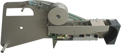
32 mm Feeder
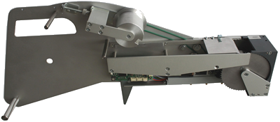
44 mm Feeder
CAN-BUS feeder cassette
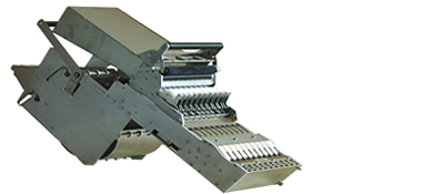
CAN-BUS feeder cassette
Space-saving feeder for component belts with 8 mm width. The feeder cassette with 10 x 8 mm feeders requires only the space of 6 x 8 mm single feeders. The
feeders are motor driven, activation via IR signal or CAN-BUS. Easy mounting because no cables or pneumatic connections have to be connected. Power is supplied
by a bus bar integrated in the feeder bank.
Linear feeder bars

Linear feeder for bar stock and mouthpieces
Feeder for SMD components supplied in bars. The components are conveyed by vibration, which is generated by a linear magnet. Easy changeover to different housing
shapes by exchanging the mouthpieces. Special designs can be realized by adapting or customizing the mouthpieces.
Label feeder

Label feeder
In order to meet the ever-increasing demand for traceability in the inoplacer line as well, we have expanded our program with the INOLABEL ALF 12 label feeder.
We see this as the ideal complement to our INORÜST (feeder setup and batch management) and INOTRACE (Traceability Compact) software modules.
Short tape board
SMD short tape board for small series assembly, exotic assembly or sample assembly. The individual belt feeding elements can be pressed into the base plate
in a 4-position grid, allowing different belt widths to be processed. The belt is threaded into the guide and fixed with a perforation hole in the catch pin.
The unit thus set up is aligned on the machine and programmed as a grid tray.
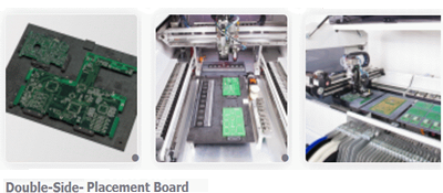
Double side placement board
Universal PCB holder for INOPLACER SMD placement machines. The PCB holding pieces are 8 mm above the base plate, thus double-sided placement is possible without
conversion. A right angle can be created via the fixed support pieces and the required board dimensions can be set via the adjustable support pieces. Eccentrically
rotatable support points prevent the PCB from bending during the assembly process.
Grid tray handler
Grid tray handler for automatic feeding of max. 10 grid trays, size max. 260 x 350 mm.
Inline system INOPLACER HPA
max. loading area 300 x 350 mm
only in connection with automatic reference mark recognition
